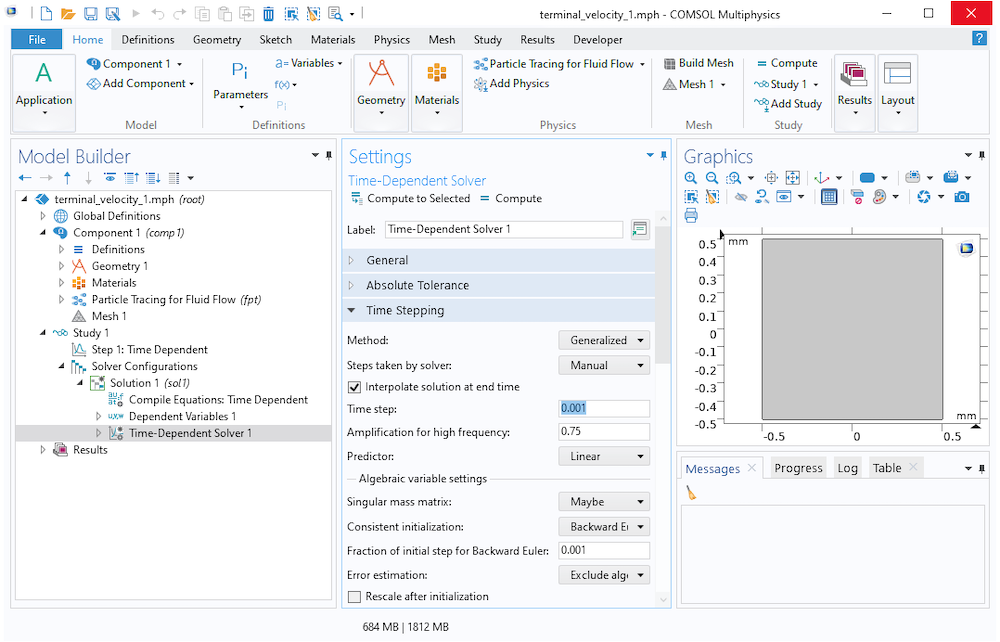

Attached the 2D cut line plot (c vs y for different x) and the resulting BL growth plot (of y for c=0,8 vs x) from Excel. Looked pretty linear in the region of c=0,8, but otherwise it is just to plot and fit a trendline and interpolate with the equation. I imported the data into excel and used the Forecast linear interpolation to determine the y-coordinate height at which the concentration was 0,8. All these curves come on the same plot, which you then can export the data from (helps to select "sort" under Advanced). Then made a 1D plot group with a 1D line graph that graphed the concentration on each x-value for the Cut Line. The geometry used to validate this model is a 0.1 m by 0. Through the study of this model, the effects of the following parameters on PCM melting interfaces have been looked at: fluid viscosity, thermal conductivity and the addition of fins.
#Adding force fluid in comsol 5.1 series#
Adding more boundary layer mesh elements might be a better way to get finer resolution in the region of interest (boundary layer) without making the whole domain finely meshed (and hence slow to solve).įor a sledgehammer approach I try defining in DataSets a 2D Cut Line, vertical at a series of x positions. used to validate this COMSOL Multiphysics model.

You could specify your own mesh (seems like you have just used a Coarse, Physics defined mesh).

The mesh is quite coarse in the boundary region, and there were only two boundary layer elements. Hopefully that means it has been incorporated into some other feature (and it is just a matter of finding what) Too much of the time I am using a slow, sledgehammer approach to do things, thinking there must be an elegant built-in function to do it.įrom a search it seems there was a feature inn earlier versions of COMSOL called postinterp() which looks like it might have something to do with it, but this does not return any hits when searching the documentation or help.


 0 kommentar(er)
